
Using Type A Earth Leakage Relays with Variable Speed Drives
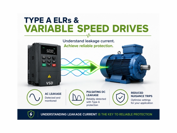
VSDs have become a standard method of controlling motor speed in industrial and commercial applications. By varying the frequency and voltage supplied to a motor, VSDs can improve energy efficiency, reduce mechanical stress and provide greater process control. However, the use of VSDs can also introduce additional leakage currents. This often raises questions about the suitability of earth leakage protection devices and can lead to the misconception that standard Type A earth leakage relays are unsuitable for use with drives.
Introduction
This application note explains how VSDs generate leakage currents, the types of leakage that may be present, and the factors to consider when selecting earth leakage protection.
Why Do VSDs Generate Leakage Current?
Unlike a conventional motor starter, a VSD uses high-frequency switching techniques to create a variable output waveform for the motor.
Several factors contribute to earth leakage current within a VSD installation:
EMC Filters
Most drives include internal EMC filters designed to reduce electromagnetic interference. These filters typically contain capacitors connected between the supply conductors and earth, creating a small but continuous leakage current path.
Motor Cable Capacitance
The longer the cable between the drive and motor, the greater the capacitive coupling between conductors and earth. This can result in increased leakage current, particularly at higher switching frequencies.
Motor Winding Capacitance
Motor windings naturally exhibit capacitance to the motor frame and earth. High-frequency voltage transitions generated by the drive can cause leakage currents to flow through these capacitances.
Switching Frequency
The pulse width modulation (PWM) technique used by VSDs creates rapid voltage changes. Higher switching frequencies can increase leakage current levels and may influence the behaviour of protection devices.
Importantly, these leakage currents are often a normal part of operation and do not necessarily indicate a fault condition.
Understanding Different Types of Leakage Current
Selecting the correct protection device requires an understanding of the type of leakage current present within the installation.
AC Leakage Current
Traditional sinusoidal alternating current leakage typically associated with standard AC systems.
Pulsating DC Leakage Current
A unidirectional leakage current whose magnitude varies over time. This type of leakage is commonly encountered in systems incorporating power electronic devices.
Smooth DC Leakage Current
A relatively steady direct current component that can occur in certain converter and rectifier topologies.
Fault Leakage Current
Leakage caused by insulation breakdown, damaged cables, moisture ingress or equipment failure. This is the condition protection devices are intended to detect.
Distinguishing between normal operational leakage and genuine fault leakage is essential to achieving reliable protection without nuisance tripping.
What Does a Type A Earth Leakage Relay Detect?
Type A Earth Leakage Relays are designed to detect:
- Sinusoidal AC residual currents
- Pulsating DC residual currents
- Mixed AC and pulsating DC fault currents
These characteristics make Type A devices suitable for a wide range of modern industrial applications where electronic power conversion equipment is present.
For many VSD applications, the dominant leakage components remain within the detection capabilities of a Type A relay.
When Is a Type A ELR Suitable for VSD Applications?
A Type A Earth Leakage Relay is often an effective solution for:
- Pump control systems
- HVAC installations
- Fan drives
- Conveyor systems
- Process automation equipment
- Water and wastewater treatment systems
- General industrial motor control applications
Where leakage currents consist primarily of AC and pulsating DC components, Type A protection can provide reliable fault detection while maintaining immunity to normal operating conditions.
Factors Affecting Earth Leakage Protection Performance
Cable Length
Long motor cables can significantly increase capacitive leakage currents. It is important to consider total cable length when selecting trip settings.
Multiple Drives
Where several drives are installed on a common supply, individual leakage currents can combine, increasing the overall residual current seen by the protection device.
EMC Filters
Drives fitted with EMC filters may exhibit higher standing leakage currents than equivalent unfiltered systems.
Environmental Conditions
Moisture, contamination and ageing insulation can gradually increase leakage current over time.
Trip Settings
Setting the trip threshold too close to the normal operating leakage level can result in nuisance tripping. Conversely, excessively high settings may reduce fault sensitivity.
Avoiding Nuisance Trips
One of the most common concerns when protecting VSD installations is nuisance tripping.
A practical approach includes:
- Measuring normal operating leakage current
- Identifying expected leakage contributions from drives and filters
- Selecting an appropriate trip threshold
- Applying a suitable time delay where required
- Monitoring trends over time
This approach helps distinguish between normal operational behaviour and developing insulation faults.
Example Application
Consider a VSD-controlled pump installation where:
- A 30 kW drive supplies an induction motor
- The motor is connected using a 40 m screened cable
- The drive incorporates an EMC filter
- Normal operating leakage current is measured at 35 mA
In this scenario, a protection device set significantly above the normal operating level can provide dependable fault detection while avoiding nuisance trips caused by routine system leakage.
Regular monitoring of leakage current trends can also provide valuable insight into the condition of cables, motors and connected equipment.
Earth Leakage Protection Solutions from Broyce Control
Broyce Control offers a range of earth leakage relays suitable for industrial motor control applications.
The ELR30PN provides Type A earth leakage protection with:
- Adjustable trip settings
- Adjustable time delays
- NFC configuration and diagnostics via smartphone
- Dual output functionality
- UL 508 listing
The ELR01PN offers highly sensitive Type A protection with trip settings down to 6 mA, making it suitable for applications requiring enhanced sensitivity.
Both devices can be used alongside appropriately selected core balance current transformers (CBCTs) to provide dependable earth leakage monitoring in VSD-driven systems.
Conclusion
The presence of a Variable Speed Drive does not automatically mean that a Type A Earth Leakage Relay is unsuitable.
Many industrial VSD applications primarily generate AC and pulsating DC leakage currents that fall well within the detection capabilities of Type A protection devices.
Understanding the sources of leakage current, establishing normal operating levels and selecting appropriate trip settings are key to achieving reliable protection while avoiding nuisance tripping.
When correctly applied, Type A Earth Leakage Relays provide an effective and economical solution for protecting VSD-driven equipment and supporting long-term system reliability.
