
Testing and Verifying Earth Leakage Relay Trip Times
Correctly testing an Earth Leakage Relay (ELR) requires more than applying a current equal to its selected trip level. The test current, intentional time delay, relay operating time and response of the associated switching device must all be considered.
An unsuitable test method can make a correctly operating ELR appear inaccurate or too slow.
Introduction
This application note explains how to apply a controlled residual current, verify instantaneous and delayed operation, and identify common causes of misleading test results.
What Does an ELR Trip-Time Test Verify?
An ELR detects the imbalance between the currents passing through its associated toroidal current transformer. When the measured residual current exceeds the selected trip level, IΔn, the relay operates after any configured time delay.
A complete test can verify:
- The ELR is powered and configured correctly
- The toroid and connecting wiring are operating correctly
- The relay responds at the intended residual-current level
- The selected time delay is functioning correctly
- The output contacts change state
- The associated contactor, shunt-trip mechanism or circuit-breaker disconnects the supply, where applicable
The scope of the test should be clearly defined. Measuring the ELR output contact alone is not the same as measuring the total disconnection time of the complete protective system.
Built-In Test Function or External Current Injection?
Built-in test function
The TEST control provided on an ELR checks certain internal functions by electrically simulating a residual-current condition. It provides a convenient functional check but does not necessarily verify:
- The installation of the external toroid
- The wiring between the toroid and ELR
- The selected residual-current threshold with a calibrated test current
- The operation of an external contactor or circuit-breaker
- The total disconnection time of the installation
The manufacturer’s instructions should always be checked to establish precisely what the built-in test function covers.
External current-injection test
An external test passes a known current through the toroid to produce a controlled residual-current signal. This allows the sensing circuit, ELR response and output operation to be tested together.
Where the ELR output controls a contactor, shunt-trip release or circuit-breaker, the test may also be extended to confirm operation of the complete protection chain.
Relevant Standards
IEC standards provide useful reference points for residual-current device performance and testing.
IEC 60755
IEC 60755:2017 establishes general minimum safety requirements and operating principles for residual-current operated protective devices intended primarily to protect against electric shock.
The familiar maximum operating-time benchmarks for a non-time-delayed 30 mA protective device include:
| Applied residual current | Maximum operating time |
| 1 × IΔn | 300ms |
| 5 × IΔn | 40ms |
The 5 × IΔn test is therefore a useful reference when verifying rapid operation at a 30mA instantaneous setting. For a selected trip level of 30mA:
Test current = 5 × 30mA = 150mA
The applicable product standard, manufacturer’s specification and intended protective function must still be considered before using these limits as pass/fail criteria.
IEC 60947-2, Annex M
IEC 60947-2 covers low-voltage circuit-breakers. Annex M addresses Modular Residual Current Devices, or MRCDs, which detect residual current but rely on an associated circuit-breaker to interrupt the protected circuit.
This is particularly relevant to an ELR installation because it distinguishes between:
- The operating time of the residual-current relay
- The operating time of the associated switching device
- The total operating time of the complete protection arrangement
- The declared non-operating time of a time-delayed device
Formal conformity with Annex M applies to a tested and declared combination of sensing means, residual-current relay and associated circuit-breaker. It should not be claimed solely because an individual ELR has been tested using similar current levels.
Applying the standards in practice
The standards provide useful reference values, but commissioning tests must also follow:
- The ELR manufacturer’s instructions
- The product’s declared operating characteristics
- The requirements of the installation
- The characteristics of the associated switching device
- Any applicable national wiring or safety regulations
Preparing the Test
Before applying a test current:
- Confirm the ELR supply voltage is correct.
- Record the selected trip level, IΔn.
- Record the selected time delay.
- Confirm that the correct toroid is fitted.
- Check the toroid-to-relay wiring.
- Confirm that all live conductors pass through the toroid.
- Ensure that the protective earth conductor does not pass through the toroid.
- Identify whether the test will measure the ELR output or complete circuit disconnection.
- Use suitable, calibrated test equipment.
- Observe the installation’s safe-isolation and commissioning procedures.
The ELR should be reset and allowed to return to its normal monitoring state before each test.
Applying the Test Current Through the Toroid
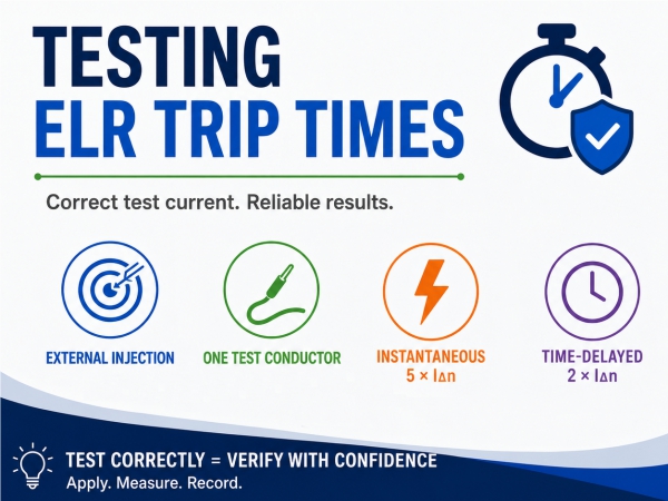
For a straightforward injection test, pass one test conductor through the toroid and apply the required current through that conductor.
Only one side of the test circuit should pass through the toroid. If both outgoing and returning test conductors pass through it, their magnetic effects will cancel and the ELR may detect little or no residual current.
Multiple test turns
If the test conductor passes through the toroid more than once, each pass acts as an additional primary turn:
Effective residual current = test current × number of turns
For example, passing a conductor through the toroid five times and applying 30mA produces an effective test current of:
30mA × 5 turns = 150mA
The number of turns must therefore be recorded and included when calculating the effective residual current.
Testing an Instantaneous Setting
For a 30 mA ELR configured with no intentional delay, apply a test current of:
5 × IΔn = 5 × 30 mA = 150 mA
The ELR should operate within its declared maximum time. A maximum of 40ms at 5 × IΔn is a recognised reference value for non-time-delayed 30mA residual-current protective devices.
Broyce Earth Leakage Relays configured for 30mA and 0s are typically designed to respond in less than 20ms under the specified test conditions. However, the applicable product data should always be used as the formal acceptance criterion.
The measured time may increase if the test includes:
- Operation of the ELR output relay
- An external contactor
- A circuit-breaker shunt-trip release
- The mechanical opening time of the switching device
- Arc-extinction time
For this reason, the test record should state clearly where the timing measurement starts and stops.
Testing an Intentional Time Delay
For Broyce ELRs with an intentional time delay, the recommended commissioning method is to apply:
2 × IΔn
Examples include:
| Selected trip level | Applied test current |
| 100mA | 200mA |
| 300mA | 600mA |
| 500mA | 1A |
| 1A | 2A |
The measured operating time should be assessed against the selected delay and the product’s specified response characteristics.
The selected delay is generally a non-operating or intentional delay period. It should not automatically be interpreted as the exact total time from application of the test current to complete circuit isolation.
The total measured time may comprise:
Total disconnection time = intentional delay + ELR operating time + switching-device operating time
For example, an ELR set to a 500ms delay will intentionally remain in its normal state during the delay period. Once that period has expired, additional time may be required for the output relay and associated circuit-breaker or contactor to operate.
Testing a delayed ELR at only 1 × IΔn can also produce less consistent results, particularly where the applied current is close to the operating threshold. Applying 2 × IΔn provides a clearer test condition for verifying the configured delay.
Operating Time Versus Total Disconnection Time
It is important to identify which time is being measured.
ELR operating time
The time between applying the residual test current and the ELR output changing state.
Switching-device operating time
The time required for the associated contactor or circuit-breaker to respond after receiving the ELR trip signal.
Total disconnection time
The time between applying the residual current and interruption of the protected circuit.
This distinction is particularly important when assessing an ELR arrangement using the principles of IEC 60947-2 Annex M. The overall protective performance depends on the complete chain:
Toroid → ELR → Output contact → Trip mechanism → Circuit interruption
A compliant ELR response does not, by itself, confirm that the complete installation will disconnect within the required time.
Allowing for Test Accuracy
Measured results can be affected by:
- Current-source accuracy
- Timer resolution
- Test-lead arrangement
- The rate at which the test current is applied
- Variations in the auxiliary supply
- Toroid installation and wiring
- Output relay response
- Contactor or circuit-breaker operating time
- Repeated testing without sufficient reset time
The applied current should be measured or generated using suitable calibrated equipment. Where results are close to the specified limit, the accuracy and uncertainty of the complete test arrangement should be considered before concluding that the ELR is outside specification.
Common Causes of Incorrect Test Results
Applying the wrong multiple of IΔn
Testing a 30mA instantaneous setting at only 30mA does not reproduce the recognised 5 × IΔn rapid-operation test condition.
Confusing the delay setting with total disconnection time
The measured result may include the ELR response, output relay and external switching-device
operating time in addition to the selected delay.
Passing both test conductors through the toroid
The outgoing and return currents cancel, preventing the intended residual current from being detected.
Incorrectly calculating multiple turns
Each pass through the toroid increases the effective residual current. Failing to include the number of turns produces an incorrect test value.
Testing only the internal function
The ELR’s TEST control may not confirm the external toroid, its connecting cable or the complete trip circuit.
Testing too close to the threshold
Small variations in test current and relay operating threshold can produce inconsistent results when the applied current is close to IΔn.
Measuring the wrong point
Timing the ELR output contact and timing complete circuit interruption are different tests and can produce significantly different results.
Incorrect ELR configuration
The selected trip level, delay, output mode or frequency-filter setting should be confirmed before testing.
Suggested Commissioning Procedure
- Record the ELR model and serial number.
- Record the associated toroid model.
- Confirm the toroid and ELR wiring.
- Record the selected trip level and delay.
- Confirm the condition and calibration status of the test equipment.
- Determine the required test-current multiple.
- Calculate the actual injection current, allowing for multiple conductor turns.
- Apply the test current as a step input.
- Record the ELR output operating time.
- Where required, record the total circuit-disconnection time separately.
- Reset the ELR and repeat the test to confirm consistency.
- Restore the installation to its normal operating condition.
Example Test Record
| Test information | Recorded result |
| ELR model | |
| ELR serial number | |
| Toroid model | |
| Selected trip level, IΔn | |
| Selected time delay | |
| Applied test-current multiple | |
| Test current | |
| Number of conductor turns | |
| Effective residual current | |
| ELR output operating time | |
| Total disconnection time | |
| Test-equipment identification | |
| Calibration due date | |
| Pass/fail criterion | |
| Result | |
| Engineer | |
| Test date |
Conclusion
Correct verification of an Earth Leakage Relay depends on applying a known residual current under clearly defined test conditions. For a 30mA instantaneous setting, testing at 5 × IΔn provides a recognised reference for verifying rapid operation. For Broyce ELRs with an intentional time delay, applying 2 × IΔn provides a practical and repeatable method of confirming the selected delay.
The ELR operating time and total circuit-disconnection time should always be recorded separately. Where the ELR operates an external contactor or circuit-breaker, the performance of the complete protection chain must be considered.
Following the product instructions, using calibrated equipment and recording the precise test arrangement will help prevent incorrect test results and unnecessary product returns.
Standards referenced
- IEC 60755:2017 — General safety requirements for residual current operated protective devices
- IEC 60947-2 — Low-voltage switchgear and controlgear – Part 2: Circuit-breakers, including Annex M for Modular Residual Current Devices
