
What Does an Insulation Fault Look Like to a Insulation Monitoring Device
An insulation fault is not always a sudden connection between a live conductor and protective earth. It may begin as a small deterioration caused by moisture, contamination, damaged cabling, ageing insulation or a failing component. The insulation resistance can then decline gradually, fluctuate with operating conditions or fall rapidly during a more serious fault.
Introduction
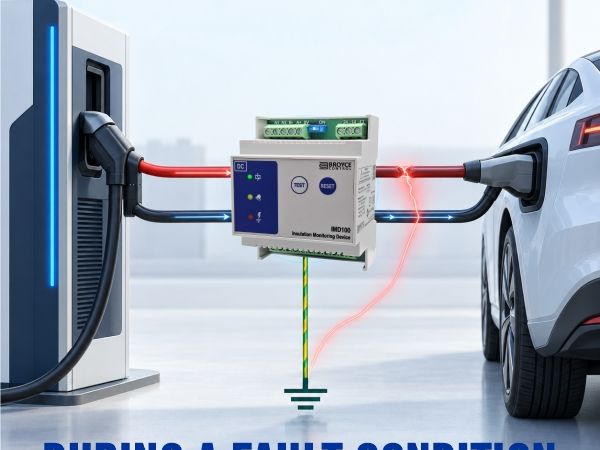
To an insulation monitoring device (IMD), the event appears as a change in the electrical relationship between the live conductors and earth. By continuously monitoring this relationship, the IMD can identify deteriorating insulation before it develops into a more serious electrical safety or operational problem.
This application note explains what an insulation fault looks like from the IMD’s perspective, how the measured values change and why the resulting warning should not be ignored.
What does an IMD monitor?
An IMD is used to monitor the insulation resistance between the live conductors of an unearthed, or IT, electrical system and protective earth. In an unearthed DC system, neither DC+ nor DC− is intentionally connected directly to earth. However, both conductors have some electrical relationship with earth through the insulation resistance of the complete installation. This includes connected cables, power electronic equipment, filters, switching devices, the vehicle and other system components. The system will also have a certain amount of capacitance to earth. This may be created by cable construction, electromagnetic compatibility filters, power electronic components and the physical arrangement of the installation.
An active IMD applies a controlled measuring signal between the monitored system and earth. It evaluates the resulting response to determine the system’s overall insulation resistance. IEC 61557-8 defines requirements for IMDs that permanently monitor insulation resistance to earth in unearthed AC and DC systems. The value observed by the IMD therefore represents the combined insulation condition of the connected system—not just one cable or component.
The healthy system
In a healthy unearthed DC system, the insulation resistance between DC+ and earth and between DC− and earth is high. This does not mean that the conductors are completely isolated from earth. Every connected component contributes some finite resistance and capacitance. When these parallel paths are combined, they produce the total insulation resistance seen by the IMD.
If the insulation resistances from DC+ and DC− to earth are represented as (R_P) and (R_N), the approximate combined insulation resistance is:
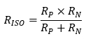
Adding more equipment to the monitored system can reduce the total measured resistance because each item introduces another potential parallel path to earth. A lower reading does not automatically indicate that a fault has occurred, provided the value remains stable and above the required response threshold.
In a reasonably balanced system, the voltages measured from DC+ to earth and from DC− to earth may each sit at approximately half the total DC-link voltage. This midpoint is not fixed, however, because the system is floating. The precise voltages depend on the resistance and capacitance between each conductor and earth.
What changes when a fault develops?
An insulation fault introduces an additional resistance path between one or both live conductors and earth. This path appears in parallel with the existing system insulation and reduces the overall resistance measured by the IMD.
From the IMD’s perspective, a fault event may therefore involve:
- a gradual reduction in insulation resistance;
- a sudden step-change to a lower resistance;
- a fluctuating or intermittent resistance;
- deterioration predominantly affecting DC+;
- deterioration predominantly affecting DC−; or
- similar deterioration on both conductors.
The IMD does not necessarily “see” the physical cause of the problem. It detects the electrical effect that the problem has on the insulation between the live system and earth. A damaged cable, contaminated connector and failing power module may all produce a similar reduction in measured insulation resistance, even though the physical causes are very different.
An asymmetrical fault on one conductor
Consider an insulation fault developing between DC+ and protective earth. As the fault resistance falls, the electrical potential of DC+ moves closer to earth potential. Because the DC system remains floating, the potential of DC− relative to earth moves in the opposite direction.
For example, in an 800 VDC system with reasonably balanced insulation:
- DC+ to earth may initially measure approximately +400 V;
- DC− to earth may initially measure approximately −400 V.
If the insulation resistance between DC+ and earth deteriorates significantly:
- the voltage between DC+ and earth moves towards 0 V;
- the voltage between DC− and earth moves towards the full 800 VDC system voltage;
- the combined insulation resistance falls.
The reverse occurs if the fault develops between DC− and earth. This voltage displacement is an important characteristic of a first insulation fault in an unearthed DC system. It also means that conductor-to-earth voltage measurements alone can be misleading. A voltage imbalance may indicate which side of the system is affected, but the IMD is needed to monitor the insulation resistance continuously and provide a reliable warning.
Although a first insulation fault may not produce a high fault current or cause immediate disconnection in an unearthed system, it should still be investigated promptly. Once one conductor has become referenced to earth, a second fault affecting the opposite conductor could establish a low-resistance current path through earth or bonded conductive parts.
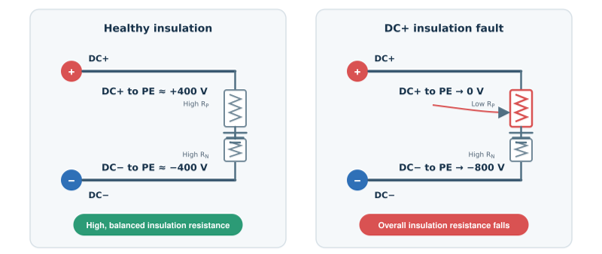
Figure 1 – Conductor to earth voltage displacement
Note: Values are illustrative. Actual conductor-to-earth voltages depend on the system insulation resistance, capacitance and connected equipment.
Symmetrical insulation deterioration
Not every insulation fault affects only one conductor. Moisture, contamination or ageing may reduce the insulation resistance of DC+ and DC− by similar amounts. This is known as symmetrical insulation deterioration. In this situation, the conductor-to-earth voltages may remain approximately balanced even though the total insulation resistance has fallen considerably. Relying only on DC+ to earth and DC− to earth voltage measurements could therefore fail to identify the developing problem.
An active IMD can detect this symmetrical reduction because it evaluates the insulation resistance of the complete system rather than relying solely on voltage displacement. This is particularly relevant in installations containing long cables, multiple power modules or equipment exposed to common environmental conditions.
A fault is not always an instantaneous event
A severe insulation breakdown may produce a sudden reduction in resistance, but many faults develop progressively.
A typical sequence could be:
- The system begins with a high and stable insulation resistance
- Moisture, contamination, mechanical damage or insulation ageing creates a new path to earth
- The measured insulation resistance begins to fall
- The value may fluctuate as temperature, vibration, switching states or environmental conditions change
- The resistance crosses the IMD response threshold
- The IMD changes the state of its alarm output and communicates the fault to the system controller
- The controller initiates the response defined by the equipment manufacturer
This early detection is one of the principal benefits of continuous insulation monitoring. The system does not need to wait for a complete short circuit to earth before a problem is identified.
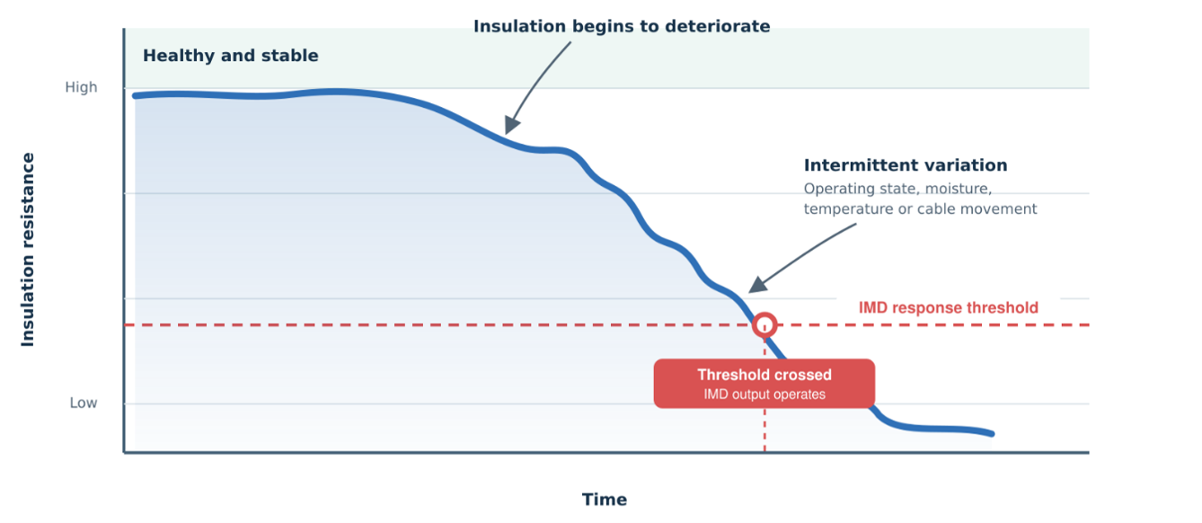
Figure 2 – How a developing insulation fault appears to an IMD
Note: An insulation fault may appear as a progressive and sometimes fluctuating reduction in resistance rather than an immediate short circuit.
What happens when the response threshold is crossed?
The IMD compares the measured insulation resistance with its configured response value. When the resistance falls below that value for the necessary response period, the IMD operates its alarm output.
Depending on the design of the IMD and the wider system, this may include:
- changing the state of an output relay;
- illuminating a warning or fault indicator;
- communicating the measured value or fault status through a serial interface;
- signalling the charger or equipment controller; or
- preventing the next operating sequence from starting
The IMD reports the condition, but it does not necessarily disconnect the monitored circuit itself. The required system response is normally performed by the equipment controller, contactors or other switching devices.
This distinction is important. The IMD provides information about the insulation condition; the overall control and protection architecture determines what happens next.
Depending on the application and operating state, the controller may:
- issue a warning;
- prevent charging or energisation;
- stop an active charging session safely;
- open the relevant contactors;
- record a diagnostic event; or
- request inspection and maintenance.
The response value, response time and resulting system action should be selected according to the application, system voltage, equipment design and applicable standards.
Why does the reading sometimes fluctuate?
A real DC installation is more complex than a fixed resistance connected between one conductor and earth.
The value displayed or communicated by an IMD may be influenced by:
- changes in the connected equipment;
- opening or closing contactors;
- connection or disconnection of a vehicle;
- switching activity from power converters;
- electromagnetic compatibility filters;
- system leakage capacitance;
- pre-charge and discharge circuits;
- moisture or contamination that changes with temperature;
- vibration affecting an intermittent connection; and
- movement of damaged cables or connectors.
The IMD’s measuring method and signal processing must distinguish a genuine change in insulation condition from the normal electrical behaviour of the system. System leakage capacitance is especially important because the IMD’s measuring signal may need time to charge and discharge the capacitance before a stable resistance value can be determined. A higher capacitance can therefore increase the measurement and response time.
A changing reading should not automatically be dismissed as electrical noise. Repeated dips, intermittent alarms or values that deteriorate during a particular operating state can provide useful evidence about where and when the fault is occurring.
Conclusion
Understanding what an insulation fault looks like from an IMD’s perspective helps engineers interpret changing resistance values, conductor-to-earth voltage displacement and intermittent events more effectively. By continuously monitoring the insulation condition of an unearthed DC system, developing faults can be identified and communicated to the system controller before they progress into a more serious condition.
The Broyce Control IMD100 provides insulation monitoring for DC systems operating up to 1000 VDC, including CCS and CHAdeMO charging applications, while the IMD125 provides monitoring for systems operating up to 1250 VDC, including higher-voltage charging architectures such as MCS.
