
Undervoltage and Overvoltage Explained – Protecting Three-Phase Equipment
Electrical equipment is designed to operate within a specified voltage range. When the supply remains above or below these limits, equipment performance, reliability and service life can be affected. Undervoltage can result in increased motor current, reduced torque and difficulty starting, while overvoltage can increase electrical and thermal stress on motors and connected equipment.
Introduction
This application note examines the causes and effects of overvoltage and undervoltage in three-phase systems and explains how continuous voltage monitoring can provide protection against prolonged abnormal supply conditions.
Variations in supply voltage are a normal characteristic of electrical distribution systems. Changes in network loading, local demand and operating conditions mean that the voltage measured at a piece of equipment will not always remain exactly at its nominal value.
Equipment is therefore designed to tolerate an acceptable range of supply voltage.
Problems arise when the voltage moves outside the limits suitable for the connected equipment and remains there for a sufficient period of time.
For motor-driven machinery, HVAC systems, pumps, compressors and industrial control equipment, sustained overvoltage or undervoltage can affect performance and place unnecessary electrical or thermal stress on components.
Continuous voltage monitoring provides a means of identifying these conditions and taking protective action before prolonged abnormal operation results in equipment damage or process disruption.
What Is Overvoltage and Undervoltage?
In the context of three-phase voltage monitoring:
- Overvoltage occurs when the measured supply voltage rises above a predetermined upper operating limit
- Undervoltage occurs when the measured supply voltage falls below a predetermined lower operating limit
For example, a monitoring system protecting equipment designed around a nominal 400 V supply might have upper and lower thresholds selected according to the acceptable operating range of the equipment.
It is important that these thresholds are based on the requirements of the load and installation, rather than simply assuming that any deviation from nominal voltage represents a fault.
A small variation from nominal voltage is normal. The objective is to identify voltage conditions that are sufficiently severe or persistent to adversely affect the equipment being protected.
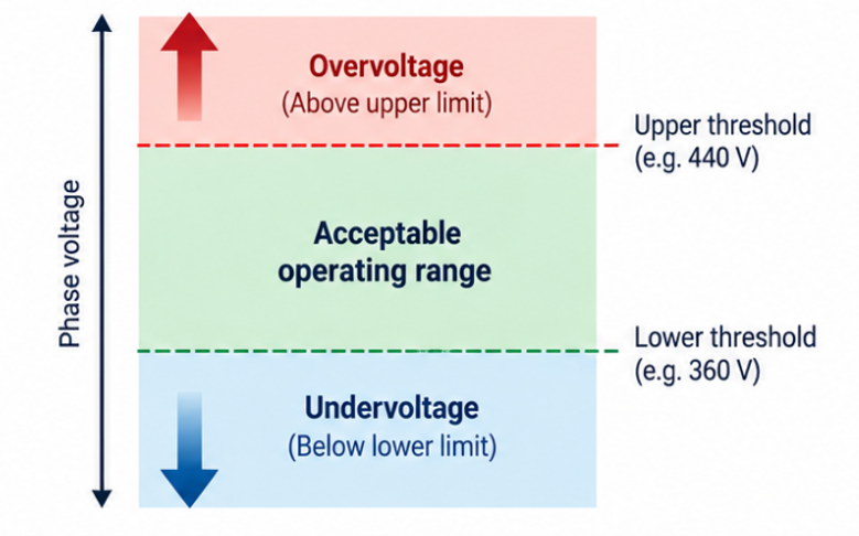
Figure 1 – How upper and lower voltage thresholds define the acceptable operating range for the connected equipment
What Causes Undervoltage?
Undervoltage can result from conditions within the wider electrical supply or from problems within the installation itself.
Typical causes include:
- Heavy loading of the electrical network
- Starting of large motors or other high-current loads
- Excessive voltage drops along cables
- Long cable runs
- Undersized conductors
- Poor or high-resistance connections
- Transformer loading or regulation issues
- Generator supply problems
- Distribution system faults
- Inadequate supply capacity
Some undervoltage conditions may only last briefly, such as the voltage dip associated with starting a large motor. Others may persist until the underlying cause is corrected.
This distinction is important when selecting both the voltage threshold and any operating delay applied to the monitoring relay.
How Does Undervoltage Affect a Three-Phase Motor?
For an induction motor, reducing the applied voltage reduces the torque the motor can develop. Motor torque is strongly dependent on applied voltage, so a comparatively modest reduction in voltage can have a much greater effect on available torque.
This can create several problems:
Difficulty starting – A motor may be unable to develop sufficient starting torque to accelerate its load.
The motor can remain at low speed or stall while drawing substantial current, resulting in rapid heating.
Increased current under load – Where a motor is required to continue delivering its mechanical load at reduced voltage, it may draw increased current. This increases losses and winding temperature.
Reduced available torque – The motor may no longer be able to drive the connected equipment reliably, particularly where the application operates close to its normal rated load.
Increased motor temperature – Higher current and prolonged operation under abnormal conditions can increase winding temperature and accelerate deterioration of the insulation system.
Unexpected process problems – A pump, compressor, conveyor or fan may continue operating but no longer deliver its expected performance.
Undervoltage should therefore not be considered simply as an electrical measurement issue; it can directly affect the operation of the machine or process.
What Causes Overvoltage?
Sustained overvoltage can also originate from several sources.
Typical causes include:
- Incorrect transformer tap settings
- Supply regulation problems
- Sudden removal of significant loads
- Generator or AVR regulation problems
- Incorrect system configuration
- Neutral-related problems in applicable distribution systems
- Distributed generation and local network conditions
- Faults within power distribution equipment
As with undervoltage, the duration of the condition is important. A sustained increase in RMS supply voltage should not be confused with a short-duration transient or surge.
How Does Overvoltage Affect Equipment?
Operating electrical equipment above its intended voltage range increases electrical stress on components and insulation. The exact consequences depend on the equipment involved.
For motors, possible effects include:
- Increased magnetic flux
- Increased core losses
- Additional heating
- Increased magnetising current
- Greater electrical stress on insulation
- Reduced equipment life if exposure is prolonged
Other connected equipment may also be affected, including control transformers, power supplies, contactor coils and electronic equipment.
A voltage level that does not cause immediate failure can still be undesirable if equipment is repeatedly or continuously operated above its intended range.
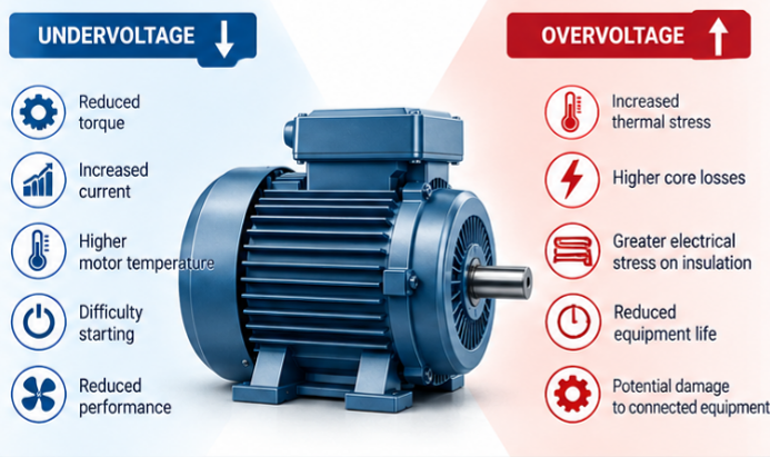
As summarised in Figure 2, both undervoltage and overvoltage can adversely affect a motor, although the resulting electrical and mechanical effects differ
Overvoltage Is Not the Same as a Voltage Surge
This is an important distinction when specifying protection.
A three-phase voltage monitoring relay is primarily intended to detect RMS supply voltage conditions that remain outside defined limits.
A transient overvoltage or surge is typically a much shorter event that may last for microseconds or milliseconds and can be caused by switching events, lightning or other electrical disturbances. These conditions require appropriate surge protective devices (SPDs) rather than relying on a voltage monitoring relay.
The two forms of protection therefore perform different functions:
| Protection | Primary Purpose |
| Voltage Monitoring Relay | Detects sustained overvoltage and undervoltage conditions |
| Surge Protective Device | Limits short-duration transient overvoltages |
Depending on the installation, both may be required.
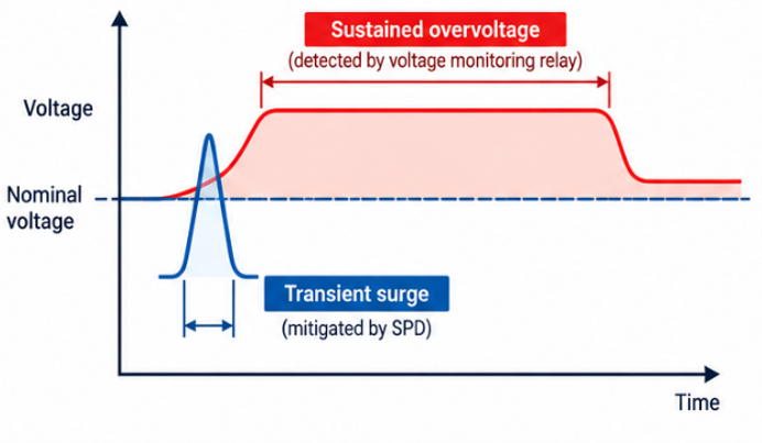
Figure 3 – Sustained Overvoltage vs Transient Surge
Why Monitoring Only One Limit May Not Be Enough
Some applications are particularly vulnerable to low voltage, while others may be more sensitive to excessive voltage. However, monitoring both upper and lower voltage limits provides a defined operating window. For example:
Upper limit
↑
Overvoltage region
────────────
Acceptable operating window
────────────
Undervoltage region
↓
Lower limit
The associated equipment is permitted to operate while the measured supply remains within the defined window. If the voltage moves outside either limit for longer than the permitted delay, the monitoring relay can initiate protective action.
This approach allows the acceptable voltage range to be matched to the requirements of the equipment rather than simply detecting complete supply failure.
The Importance of Time Delays
Not every voltage excursion should result in an immediate shutdown. Temporary voltage dips can occur when:
- Large motors start
- Transformers are energised
- Heavy loads are switched
- Supply networks experience short-duration disturbances
If the monitoring relay responded instantaneously to every short excursion, unnecessary or nuisance tripping could occur.
An adjustable time delay allows brief disturbances to be tolerated while ensuring that a persistent overvoltage or undervoltage condition results in protective action.
The appropriate delay depends on:
- The equipment being protected
- The severity of the voltage deviation
- The expected characteristics of the supply
- The ability of the equipment to tolerate the abnormal condition
Protection settings should therefore be selected according to the application rather than simply using the most sensitive voltage and shortest time settings available.
Hysteresis and Recovery
Another consideration is what happens when the supply voltage returns towards its normal value.
If a relay were to switch at exactly the same voltage at which it originally operated, a supply fluctuating around the threshold could cause repeated switching or relay chatter.
Monitoring relays therefore commonly incorporate hysteresis between the operating and reset levels.
For example, after an undervoltage trip, the voltage may need to recover sufficiently above the original threshold before the relay resets.
Similarly, following an overvoltage condition, the voltage must fall sufficiently back into the acceptable range.
This provides stable operation around the switching thresholds.
Where equipment automatically restarts following voltage recovery, the wider machine control and safety requirements should also be considered before automatic restart is permitted.
Overvoltage, Undervoltage and Voltage Imbalance
Voltage magnitude and voltage imbalance are related but separate characteristics of a three-phase supply.
A system could have:
- Three balanced voltages that are all too low
- Three balanced voltages that are all too high
- An acceptable average voltage but excessive imbalance between phases
- A combination of voltage magnitude and imbalance faults
For example:
390 V / 400 V / 410 V
may have an acceptable average voltage of 400 V while still exhibiting voltage imbalance.
Conversely:
350 V / 351 V / 349 V
could be well balanced between phases but represent an unacceptable undervoltage condition for the connected equipment.
This demonstrates why comprehensive three-phase monitoring may include both upper/lower voltage limits and voltage imbalance detection.
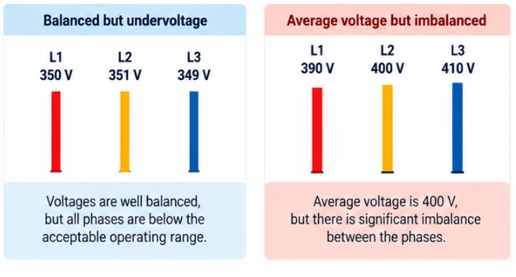
Figure 4 – Balanced vs Imbalanced
Continuous Three-Phase Voltage Monitoring
A three-phase voltage monitoring relay continuously supervises the incoming supply. Under healthy conditions, with the voltage inside the selected operating limits, the output relay allows the associated control circuit to operate normally.
If the voltage rises above the overvoltage threshold or falls below the undervoltage threshold for longer than the selected delay, the output changes state.
This can be used to:
- De-energise a contactor
- Prevent equipment from starting
- Stop machinery before prolonged abnormal operation
- Initiate an alarm
- Signal the fault to a control or monitoring system
Once the supply returns to an acceptable level, the relay can reset according to its specified recovery characteristics.
Selecting the Appropriate Protection
Overvoltage and undervoltage monitoring will often form part of wider three-phase supply protection.
Depending on the application, monitoring may include:
- Overvoltage
- Undervoltage
- Voltage imbalance
- Phase loss
- Phase sequence
The correct combination depends on the equipment.
A pump motor where rotation must always remain in one direction may benefit from comprehensive monitoring including phase sequence.
An application intentionally designed for forward and reverse motor operation may require overvoltage, undervoltage, imbalance and phase-loss protection without phase sequence monitoring.
The monitoring relay should therefore be selected according to the actual requirements of the machine rather than simply choosing the device with the greatest number of functions.
Commissioning and Troubleshooting
When commissioning an overvoltage/undervoltage monitoring system, verify that:
- The nominal system voltage is correctly identified
- Upper and lower thresholds suit the connected equipment
- Any time delay is appropriate for normal supply disturbances
- The output relay operates correctly when a limit is exceeded
- The associated contactor or control system responds correctly
- Reset behaviour is appropriate when normal voltage returns
Where unexpected trips occur, the monitoring relay should not automatically be assumed to be the cause.
Measurements should be taken to establish whether the supply is genuinely moving outside the selected limits and, if so, why.
Repeatedly widening thresholds to prevent tripping can mask an underlying supply or installation problem.
Conclusion
Overvoltage and undervoltage represent two different but important supply conditions that can affect the performance, reliability and service life of three-phase electrical equipment.
Undervoltage can reduce motor torque and lead to increased current, excessive heating or difficulty starting, while sustained overvoltage can increase magnetic, thermal and insulation stress on motors and other connected equipment.
Continuous three-phase voltage monitoring allows acceptable upper and lower operating limits to be defined, enabling protective action when the supply remains outside those limits for an unacceptable period.
Broyce Control offers a range of three-phase voltage monitoring relays for industrial equipment and machinery. Models within the LXPRT and LXPRC/S ranges provide monitoring options for overvoltage and undervoltage alongside other three-phase supply conditions, allowing the required protection functions to be selected according to the application.
When compared with the value of the motor, machinery and process being protected, voltage monitoring represents a relatively small investment that can help prevent equipment damage and costly unplanned downtime.
Related Engineering Guides
- Why Phase Sequence Matters
- Understanding Phase Loss
- Protecting Against Voltage Imbalance
- Undervoltage and Overvoltage Explained (this guide)
- Selecting the Right Three-Phase Monitoring Relay
