
Protecting Against Voltage Imbalance
Voltage imbalance occurs when the three phase-to-phase voltages of a three-phase supply are not equal. Although the difference between phases may appear relatively small, the resulting current imbalance within a three-phase motor can be considerably greater, leading to increased heating, reduced efficiency, lower available torque and premature insulation deterioration.
Introduction
This application note examines the causes and effects of voltage imbalance, how it should be assessed, and how continuous three-phase voltage monitoring can help protect motors and other valuable equipment.
A three-phase motor is designed to operate from a balanced supply, with the three phase voltages of similar magnitude and displaced by approximately 120 electrical degrees. In practice, however, the supply is rarely perfectly balanced. Small differences between the three phase voltages are common and may have little practical consequence. Problems arise when the imbalance becomes sufficiently large to adversely affect the connected equipment.
For three-phase motors in particular, voltage imbalance deserves attention because a relatively small variation in supply voltage can produce a much larger imbalance in the motor currents.
The result can be additional heating and reduced motor performance even though all three phases are present and individual voltage measurements may initially appear acceptable.
What is Voltage Imbalance?
Voltage imbalance describes a condition where the voltage magnitudes of a three-phase supply are not equal. For example, rather than measuring three similar line-to-line voltages, an installation might show:
- L1–L2: 400 V
- L2–L3: 390 V
- L3–L1: 410 V
All three phases are present and none of these measurements alone necessarily indicates an obvious supply failure. However, the motor is no longer being supplied by a balanced three-phase voltage.
Voltage imbalance should therefore be considered separately from conventional undervoltage or overvoltage protection. The average supply voltage may be acceptable while the difference between the individual phase voltages is not.
As illustrated in Figure 1 below, voltage imbalance can exist even though all three phases remain present.
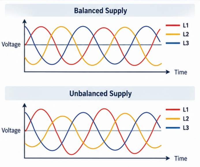
Figure 1 – Comparison of balanced and unbalanced three-phase supply voltages
What Causes Voltage Imbalance?
Voltage imbalance can originate from either the electrical supply or the installation itself.
Common causes include:
- Uneven distribution of single-phase loads across a three-phase system
- Heavily loaded phases
- Loose or deteriorating electrical connections, high-resistance contacts
- Faults within distribution equipment, cable or termination problems
- Transformer or supply-side issues
- Unequal conductor impedances
- Large single-phase loads being connected or disconnected
- Developing phase-loss conditions
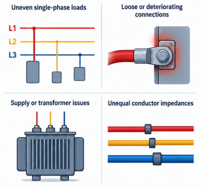
Figure 2 – Examples of conditions that can contribute to voltage imbalance
This is important from a maintenance perspective. Voltage imbalance may not simply be a characteristic of the incoming supply; it can also provide an indication that a connection or component within the installation is deteriorating.
Why Does a Small Voltage Imbalance Matter?
This is where voltage imbalance becomes particularly important for motor applications. Three-phase induction motors have a relatively low impedance to the negative-sequence component created by an unbalanced supply. Consequently, a comparatively small voltage imbalance can produce a substantially greater current imbalance in the motor windings.
A commonly used engineering rule of thumb is that the percentage current imbalance can be several times greater than the percentage voltage imbalance. The exact relationship depends on the motor and operating conditions, so a fixed multiplier should not be treated as universally applicable. The important point is that a voltage difference that appears relatively insignificant when measured at the supply can have a disproportionately large effect on the motor.
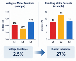
Figure 3 – A relatively small supply voltage imbalance can result in a considerably greater imbalance in motor current (Illustrative example)
Calculating Percentage Voltage Imbalance
A commonly used method expresses voltage imbalance as the maximum deviation from the average of the three line-to-line voltages:
Voltage Imbalance (%) = Maximum deviation from average voltage ÷ Average voltage × 100
Using the previous example:
- L1–L2 = 400 V
- L2–L3 = 390 V
- L3–L1 = 410 V
Average voltage: (400 + 390 + 410) ÷ 3 = 400 V
Maximum deviation from the average: 10 V
Therefore: Voltage Imbalance = (10 ÷ 400) × 100 = 2.5%
Although the average voltage is exactly 400 V, the supply has a voltage imbalance of 2.5%. This illustrates why simply checking that the average supply voltage is within an acceptable range is not sufficient to identify an imbalance condition.

Figure 4 – Voltage Imbalance Calculation
Note: Different standards and monitoring devices may define or calculate voltage imbalance using different methods. The calculation method and applicable equipment manufacturer’s requirements should therefore be confirmed when specifying protection settings.
Effect on Three-Phase Motors
Operating a motor from an unbalanced supply can produce several undesirable effects.
Increased winding temperature
Unequal phase currents result in additional losses within the motor. This increases winding temperature and places greater thermal stress on the insulation system.
Reduced motor life
Motor insulation life is strongly influenced by operating temperature. Persistent overheating can therefore accelerate insulation ageing and contribute to premature winding failure.
Reduced available torque
Voltage imbalance can reduce the torque available from the motor. This can become particularly important where the motor is already operating close to its rated load.
Reduced efficiency
Additional losses caused by unbalanced currents reduce operating efficiency and can increase energy consumption.
Increased noise and vibration
An unbalanced electrical supply can result in additional torque pulsations, which may contribute to increased vibration and audible noise.
Nuisance operation of motor protection
Higher current in one or more phases may cause overload protection to operate even though the mechanical load itself has not changed.
Voltage Imbalance and Motor Derating
Where significant voltage imbalance cannot be eliminated, the motor may need to operate below its normal rated load. Motor manufacturers and applicable standards should be consulted to determine whether derating is required for a particular level of imbalance.
This is an important distinction: simply increasing an overload setting to prevent nuisance tripping is not a suitable solution to an underlying voltage imbalance. Where possible, the cause of the imbalance should first be identified and corrected. Continuous monitoring can help identify when the condition exceeds an acceptable limit and prevent prolonged operation under potentially damaging conditions.
Voltage Imbalance vs Phase Loss
Voltage imbalance and phase loss are closely related, but they should not be considered the same fault.
With voltage imbalance, all three phases remain present, but their voltage magnitudes differ beyond an acceptable limit. With phase loss, one phase is effectively absent. Phase loss can therefore be regarded as an extreme supply abnormality, whereas voltage imbalance allows developing problems to be detected before complete loss of a phase occurs in some fault scenarios.
For example, a deteriorating connection may introduce increasing resistance, causing the voltage on one phase to deviate progressively before the connection eventually fails completely.
Monitoring both conditions provides more comprehensive protection than phase-loss detection alone.
Why Overvoltage and Undervoltage Monitoring May Not Detect It
Consider again a nominal 400 V system measuring: 390 V – 400 V – 410 V
If the undervoltage and overvoltage limits are sufficiently wide, all three measurements may remain inside the permitted operating window. An overvoltage/undervoltage relay may therefore regard the supply as acceptable.
A relay incorporating dedicated voltage imbalance monitoring, however, compares the relationship between the three phase voltages and can respond when the difference exceeds the selected limit.
This is why the required monitoring functions should be considered according to the equipment being protected rather than assuming that basic upper and lower voltage limits provide complete supply supervision.
Continuous Voltage Imbalance Monitoring
A three-phase voltage monitoring relay can continuously supervise the supply and compare the phase voltages against a predetermined imbalance threshold.
Under healthy conditions, the output relay permits the associated control circuit to operate normally.
If the imbalance exceeds the permitted level for the specified period, the relay changes state. This can be used to:
- De-energise a motor contactor
- Prevent equipment from starting
- Initiate an alarm
- Signal the condition to a control system
Where an adjustable time delay is provided, short-duration disturbances can be tolerated while persistent imbalance conditions result in protective action. This can help avoid unnecessary trips caused by transient supply disturbances while still protecting equipment from sustained abnormal operation.
Selecting the Appropriate Monitoring Functions
As with the other topics in this series, not every application requires the same combination of monitoring functions.
Depending on the equipment and installation, three-phase supply monitoring may include:
- Voltage imbalance
- Phase loss
- Phase sequence
- Undervoltage
- Overvoltage
For motor-driven equipment, combining voltage imbalance and phase-loss monitoring can be particularly valuable because it provides protection against both partial deterioration of the supply and complete loss of a phase.
Phase sequence monitoring should be selected where the direction of rotation must remain fixed. Where intentional reversal forms part of normal machine operation, a relay without phase sequence detection may be more appropriate.
Commissioning and Troubleshooting
When investigating a suspected voltage imbalance condition, measurements should be taken between all three phase combinations rather than relying on a single line-to-line measurement.
Check:
- L1–L2
- L2–L3
- L3–L1
If an imbalance is identified, the investigation should consider both the incoming supply and the installation.
Useful checks include:
- Measuring the supply with the load disconnected where appropriate
- Inspecting terminals and connections
- Checking contactor and switchgear contacts
- Reviewing the distribution of single-phase loads
- Comparing motor phase currents
- Checking whether the imbalance changes with load
The objective should be to determine why the voltages are unequal, rather than simply resetting or widening the protection limits.
Conclusion
Voltage imbalance can be easy to overlook because all three phases remain present and the individual voltage measurements may appear reasonably close to nominal. However, for a three-phase motor, even a relatively small supply imbalance can produce a much greater current imbalance, increasing motor temperature and potentially reducing performance and service life.
Continuous three-phase voltage monitoring provides a means of identifying unacceptable imbalance before prolonged operation results in motor damage or unexpected downtime.
Broyce Control offers a range of three-phase voltage monitoring relays for industrial equipment and machinery. Models such as the LXPRT and LXPRC/S can provide monitoring of three-phase supply conditions, with the appropriate model and functions selected according to the requirements of the application.
Considering the value of the motors, machinery and processes being protected, supply monitoring represents a relatively small additional investment that can help identify potentially costly electrical problems at an early stage.
Related Engineering Guides
- Why Phase Sequence Matters
- Understanding Phase Loss
- Protecting Against Voltage Imbalance (this guide)
- Overvoltage and Undervoltage Explained
- Selecting the Right Three-Phase Monitoring Relay
