
How to Select Earth Leakage Relay Trip Levels and Non-Operate Time Delays
Every electrical installation has different protection requirements, which means there is no single “correct” trip level or time delay for an Earth Leakage Relay (ELR). The optimum settings are influenced by the location of the relay within the electrical distribution system, the size of the current transformer (CBCT), the type of protection required and the characteristics of the installation itself.
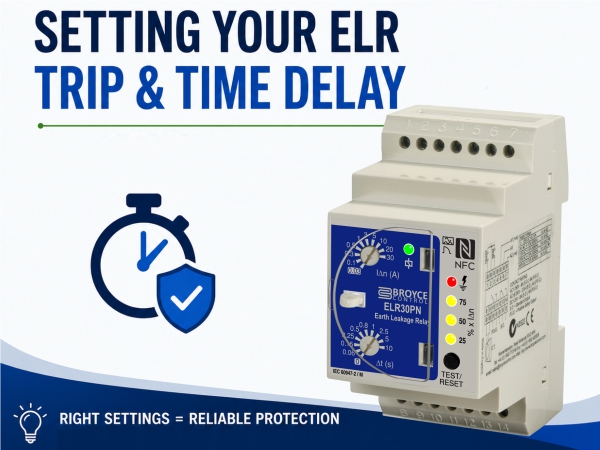
Introduction
Selecting settings that are too sensitive can result in nuisance tripping and unnecessary downtime, while settings that are too high or excessively delayed may reduce the level of protection provided. By understanding the factors that influence these settings, engineers can achieve the right balance between personnel safety, equipment protection, fire prevention and system availability.
This application note explains the key considerations when configuring an Earth Leakage Relay and provides a simple step-by-step approach to selecting suitable trip and time delay settings.
Understand the Protection Objective
Before selecting any settings, the first question should always be: What is the relay intended to protect?
The answer determines both the trip level and the acceptable operating time. Protection objectives generally fall into four categories.
- Personnel Protection
Where protection against electric shock is the primary requirement, low trip settings are normally used to disconnect the supply as quickly as possible.
Typical characteristics include:
- Low trip threshold
- Instantaneous operation
- Maximum protection for personnel
- Normally installed on final circuits
Typical trip level: 30 mA (or less)
Time delay: None (instantaneous)
Note: Certain applications require even lower trip levels such as 10 mA, or even 6 mA to use as protection against electric shock.
- Additional Personnel Protection
Some industrial installations require protection where standing leakage currents prevent the use of 30 mA devices. In these situations, a higher trip setting may be appropriate while still providing an additional level of protection.
Typical trip level: 100 mA
Time delay: Instantaneous
- Equipment Protection
Many Earth Leakage Relays are installed to detect insulation deterioration before equipment damage occurs.
Examples include:
- Motors
- Pumps
- Compressors
- Variable Speed Drives
- Industrial machinery
- EV chargers
The objective is often to prevent costly downtime rather than provide personnel protection.
Typical trip settings: 300–500 mA
Time delay: Often a short intentional delay to prevent nuisance tripping caused by transient leakage currents.
- Fire Protection
Persistent earth leakage currents can generate heat within damaged insulation and electrical connections.
Fire protection applications generally use higher trip settings than personnel protection while allowing brief transient leakage currents to pass without unnecessary interruption.
Typical trip settings: 300–500 mA
Time delay: Short intentional delay.
Consider Where the Relay Is Installed
The position of the ELR within the electrical distribution system has a significant influence on the settings.
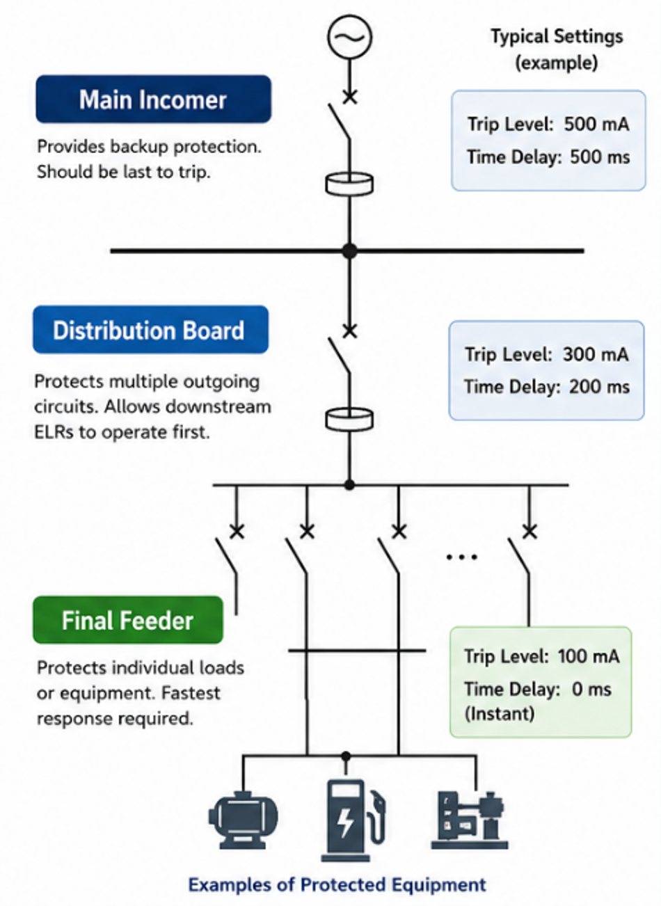
Figure 1: Typical locations for Earth Leakage Relay
Main Incoming Supply
The incomer should normally be the last protective device to operate. Its purpose is to provide backup protection if downstream devices fail to clear the fault.
Typical characteristics:
- Higher trip setting
- Longer intentional delay
- Maintains supply continuity
Distribution Board
Distribution boards often supply several outgoing feeders. If one feeder develops an earth fault, it is preferable for the downstream ELR to trip first rather than disconnecting the entire board. For this reason, a modest time delay is often introduced.
Typical characteristics:
- Medium trip setting
- Short intentional delay
- Improved discrimination
Final Outgoing Feeder
These circuits usually supply:
- One machine or motor
- One EV charger
- One distribution circuit
Since there are no downstream protective devices to coordinate with, the relay is normally configured for the fastest possible response.
Typical approach:
- Lowest practical trip level
- Instantaneous operation
Selecting the Correct Toroid (CBCT)
One of the most overlooked aspects of an ELR installation is the choice of current transformer. The toroid must be selected to suit the maximum load current of the protected circuit, but this also influences the minimum earth leakage current that can be measured reliably.
As the toroid diameter/size increases, sensitivity reduces because the magnetic path becomes larger. For this reason, manufacturers specify a minimum recommended trip setting for each toroid size. Attempting to operate below this value may result in inconsistent or unreliable tripping.
For example:
| Toroid | Typical Load | Minimum Recommended Trip* |
| 35 – 50 mm dia. | Small feeders | Very low settings possible |
| 70 – 160 mm dia. | Distribution circuits | Medium settings |
| 210 mm dia. | Large feeders | Higher minimum trip level |
| 300 mm dia. or rectangular sizes | Main incomers | Highest minimum setting |
* Always refer to the toroid data sheet for the exact values.
This is an important consideration that is often overlooked when selecting relay settings.
Consider Standing Leakage Current
Modern electrical equipment naturally produces earth leakage currents during normal operation.
Common sources include:
- EMC suppression filters
- Variable Speed Drives
- UPS systems
- Switched-mode power supplies
- EV chargers
- Long cable runs
- Power conversion equipment
If the relay trip level is set too close to the normal standing leakage current, nuisance tripping is likely.
As a guide, the normal leakage current should remain comfortably below the selected trip level to allow for normal operating variations.
Selecting the (Non-Operate) Time Delay
The non-operate delay (sometimes referred to as trip or intentional time delay) defines how long the measured earth leakage current must remain above the selected trip level before the relay operates.
Unlike a simple delay timer, the ELR continuously monitors the leakage current. If the fault clears before the non-operate delay has expired, the relay will not trip. This helps prevent unnecessary tripping caused by short-duration transient leakage currents.
Typical sources of transient leakage include:
- Motor starting
- Variable Speed Drives (VSDs)
- EMC filter charging currents
- Capacitor charging
- Switching transients
The non-operate delay also plays an important role in discrimination (selectivity) between multiple Earth Leakage Relays installed within the same electrical distribution system. By applying progressively longer delays to upstream devices, downstream relays are given the opportunity to clear the fault first, helping to minimise unnecessary loss of supply.
Personnel Protection
Where personnel protection is required, particularly at 30 mA or below, the applicable installation standards generally require instantaneous operation. For this reason, an intentional non-operate delay is not normally permitted.
All Broyce Earth Leakage Relays automatically provide instantaneous operation whenever the trip level is set to 30 mA or below, regardless of the configured time delay setting. This ensures compliance with the requirements for personnel protection while simplifying commissioning and reducing the risk of incorrect configuration.
Equipment and Fire Protection
Where the relay is used for equipment protection, fire protection or as part of a discrimination scheme, a suitable non-operate delay may be introduced to:
- Improve selectivity with downstream protective devices
- Reduce nuisance tripping caused by transient leakage currents
- Maintain continuity of supply by ensuring only the affected circuit is disconnected
As a general guide:
| Installation Position | Typical (Non-Operate) Delay |
| Final outgoing circuit | Instantaneous (0 ms) |
| Distribution feeder | Short intentional delay (>60ms) |
| Main incomer | Longer intentional delay for coordination |
The final delay setting should always be selected according to the application, the required level of protection and the applicable installation standards.
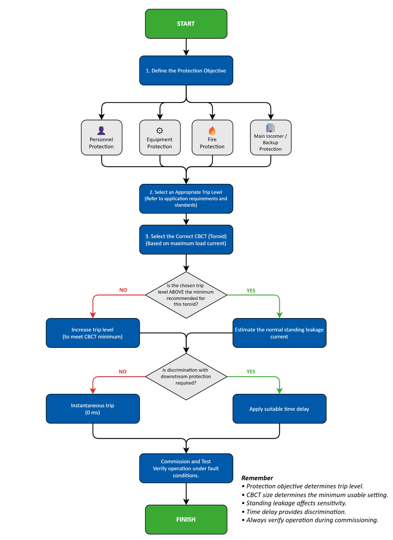
Figure 2: Selection Flowchart
A Practical Selection Process
The following sequence provides a logical method of selecting ELR settings:
- Identify the protection objective
- Select a toroid suitable for the load current
- Check the toroid’s minimum recommended trip setting
- Estimate the installation’s normal standing leakage current
- Choose a trip level above the expected leakage current
- Decide whether coordination with downstream protection is required
- Select an appropriate time delay
- Commission and test the installation under fault conditions
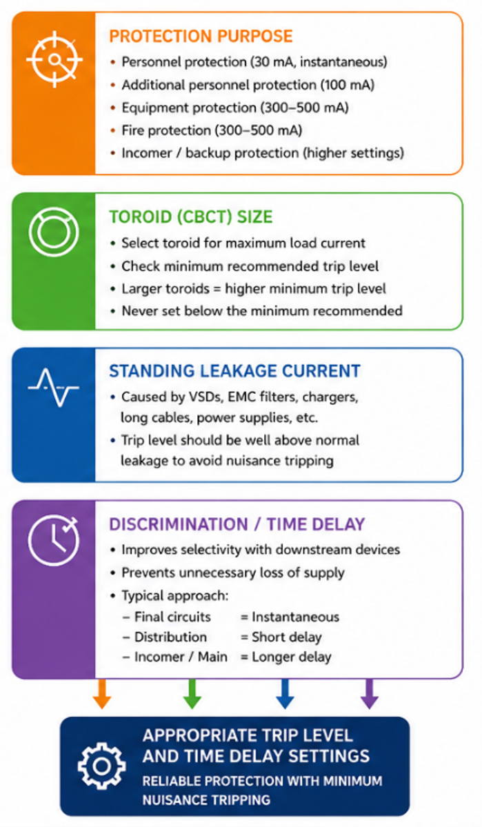
Figure 3: Key factors for setting

Key Design Considerations
When configuring an Earth Leakage Relay, always consider the following:
✓ Purpose of protection
✓ Position within the electrical distribution system
✓ Toroid size and minimum recommended trip level
✓ Standing leakage current
✓ Required level of discrimination
✓ Local wiring regulations and applicable product standards
✓ Commissioning and routine testing
Commissioning and Functional Testing
Correct commissioning is essential to verify that the Earth Leakage Relay and associated current transformer (CBCT) have been installed correctly and operate within the specified performance requirements.
One of the most common causes of apparent “trip time” issues is the application of an incorrect test current during commissioning. The relay response depends on both the selected trip level and the purpose of the test being performed.
Verifying Instantaneous Operation
For personnel protection applications, where the trip level is set to 30 mA or below with no intentional non-operate delay, the applicable product standards specify that the relay should be tested using a current equal to five times (5 ×) the selected trip level.
For example:
- Selected trip level: 30 mA
- Applied test current: 150 mA (5 × IΔn)
Under these conditions, the relay is required to operate within the maximum trip time defined by the relevant standard (typically 40 ms).
Broyce Earth Leakage Relays typically operate in less than 20 ms under these conditions, providing a fast response for personnel protection applications.
Verifying the Non-Operate Delay
Where an intentional non-operate delay has been configured, the objective of the commissioning test changes. Instead of verifying instantaneous operation, the test confirms that the relay operates after the selected delay.
In this case, the relay should be tested using a current equal to twice (2 ×) the selected trip level.
For example:
- Selected trip level: 300 mA
- Applied test current: 600 mA (2 × IΔn)
Using 2 × the selected trip level ensures the relay operates consistently while allowing the configured non-operate delay to be accurately verified.
Applying significantly higher test currents when checking delayed operation may produce misleading results and should not be used to verify the configured delay setting.
Technical Note
During commissioning, always distinguish between trip time verification and non-operate delay verification. These are different tests and require different applied test currents. Using the incorrect test current may lead to misleading results and the incorrect conclusion that the relay is operating outside its specification.
Commissioning Checklist
When commissioning an Earth Leakage Relay:
✓ Confirm the correct CBCT has been installed
✓ Verify the trip level is appropriate for the application
✓ Check that the configured non-operate delay matches the protection philosophy
✓ Use 5 × the selected trip level when verifying instantaneous operation (30 mA or below)
✓ Use 2 × the selected trip level when verifying intentional non-operate delays
✓ Confirm the relay operates within the specified performance limits before placing the installation into service
Conclusion
Correctly configuring an Earth Leakage Relay involves much more than selecting a convenient trip current. The relay, current transformer and electrical installation must be considered together to ensure dependable operation.
By assessing the protection objective, installation position, toroid selection and expected leakage current, engineers can select settings that provide reliable protection while minimising nuisance tripping and maintaining continuity of service.
