
What Does an IMD Experience During Every DC Charging Session?
Every DC charging session presents an insulation monitoring device (IMD) with a changing electrical environment. As the vehicle connects, contactors operate and power transfer begins, the circuit under supervision can change in size, insulation resistance and capacitance to earth. Throughout these transitions, the IMD must assess the insulation condition and provide information that allows the charger to respond appropriately.
Introduction
This application note follows a typical charging session which the driver’s perspective, DC charging appears straightforward: connect the cable, start charging and disconnect when finished. Inside the charger, however, a coordinated sequence of communication, electrical checks and switching operations takes place.
The IMD monitors insulation resistance between the unearthed DC circuit and protective earth (PE). Its role continues beyond the initial checks: it must monitor the electrically connected circuit as operating conditions change throughout the session.
The following stages illustrate a typical session. The precise sequence and the parts of the circuit included in each measurement depend on the charger architecture, contactor arrangement and charging protocol.
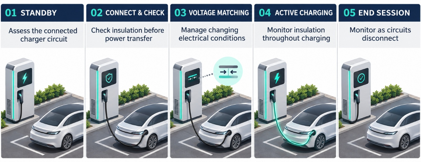
Figure 1 – The main stages of a typical DC charging session and the changing conditions encountered by the IMD
Before connection: monitoring the available circuit
Before a vehicle is connected, the IMD can assess the insulation of the charger circuitry electrically connected to its measuring terminals, provided the monitoring function is powered and enabled.
This may include the DC output circuitry and, depending on the switching arrangement, the charging cable and connector. Sections isolated by open contactors may remain outside the measurement.
At this stage, reduced insulation resistance could indicate moisture, contamination, damaged wiring or deterioration within the connected equipment.
The important point is that the IMD monitors an electrical circuit, rather than everything physically installed within the charger. Its coverage depends on which components are connected in that operating state.
Vehicle connection: the monitored circuit begins to change
Plugging in the connector establishes the physical connection between charger and vehicle. It does not necessarily connect the vehicle battery immediately. Communication and safety checks take place before the relevant high-voltage contactors close.
As the switching sequence progresses, additional circuit sections may become connected to the IMD. These introduce their own insulation resistance and capacitance to earth. Consequently, a reading taken before connection may differ from one obtained later in the session—even when both conditions are acceptable.
Once charger and vehicle circuits are electrically joined, their insulation-monitoring functions must also be coordinated. Multiple active IMDs on the same connected circuit can interfere with one another, so the charging architecture must manage which device performs the measurement.
Before power transfer: establishing an acceptable insulation condition
Before charging proceeds, the charger must establish that the relevant circuit satisfies its insulation requirements. The IMD contributes by measuring insulation resistance and reporting the resulting condition to the control system. The controller uses this information alongside the other required checks to determine whether the charging sequence can continue.
A suitable measurement must be available for the circuit configuration being assessed. A satisfactory reading from an earlier state does not automatically demonstrate that components connected subsequently are also satisfactory. If an unacceptable insulation condition is detected, the charger should inhibit further progression in accordance with its protection strategy.
Voltage matching and contactor operation: measuring through transitions
During voltage matching, pre-charge where applicable, and contactor operation, the IMD encounters further changes in the connected circuit. DC conductor voltages relative to earth can move, and capacitances associated with cables, filters and connected equipment may charge or discharge. These effects can influence the measurement while the system settles.
Why capacitance matters
Insulation resistance and capacitance to earth are different electrical properties. Insulation resistance represents resistive leakage paths between the live circuit and earth. Capacitance can exist in healthy equipment because of cable construction, filtering components and the physical arrangement of conductors. The IMD’s measuring signal interacts with both. Capacitive charging effects can therefore influence the time needed to determine a stable resistance value. Measurement and response times must be considered under the actual system conditions.
A change in reading during a switching event does not, by itself, prove an insulation fault. Equally, a recurring drop should be investigated rather than automatically attributed to a transient.
Active charging: continuous monitoring in a changing environment
Once power transfer begins, the IMD supervises the connected charging circuit while the charger regulates its output.
During this period:
- Charging voltage and current change
- Power converters generate switching disturbances
- Cables, connectors and internal components warm up
- Cooling systems operate
- Existing insulation weaknesses may become apparent under operating conditions
The IMD measures insulation resistance; it does not measure the charging current flowing into the battery. Its task is to identify an unacceptable resistive path between the monitored live circuit and earth while operating within this changing environment.
This explains why a satisfactory initial check cannot replace continuous monitoring. A fault may develop—or become detectable—after charging has started.
An insulation fault develops: turning measurement into action
An insulation fault may appear suddenly or develop gradually. Possible causes include moisture in a connector, contamination, damaged cable insulation or deterioration within the connected charger or vehicle circuitry.
When the measured insulation resistance falls below a configured threshold, the IMD reports the condition according to its measurement and response characteristics. The surrounding charger control system then performs the required action. Depending on the operating state and protection design, this may include preventing charging, stopping power transfer, opening contactors and recording a fault.
The IMD’s signalling outputs do not themselves interrupt the main charging current. Effective protection depends on the measurement being integrated with the controller and switching equipment.
An insulation alarm also does not automatically identify the faulty component. It indicates an unacceptable condition somewhere within the circuit connected to the IMD at that time.
Charging ends: the monitored circuit changes again
At the end of a normal session, charging current is reduced, switching devices operate and the appropriate discharge sequence takes place. As circuit sections disconnect, the insulation resistance and capacitance presented to the IMD can change again. A reading may recover after the vehicle is isolated because the circuit responsible for the reduced resistance is no longer included in the measurement.
This can provide useful diagnostic evidence, but it does not establish the fault location by itself.
The switching arrangement and the timing of the event must also be considered. Similarly, a satisfactory insulation reading does not confirm that the charging connector is free of hazardous voltage. Voltage verification and discharge supervision are separate functions within the charger’s safety architecture.
What can session data reveal?
Recording insulation measurements alongside charging states can make intermittent problems easier to investigate.
| Observed behaviour | Possible direction for investigation |
| Low insulation resistance before the vehicle circuit is connected | Charger circuitry, cable or connector included in that measurement |
| Resistance falls when an additional circuit section connects | Components introduced at that switching stage |
| Resistance decreases as charging progresses | Temperature-dependent deterioration or conditions emerging during operation |
| Brief disturbances repeatedly coincide with switching | Switching effects, capacitance, interference or an intermittent fault |
| Resistance recovers after vehicle isolation | A condition associated with the disconnected circuit; further investigation is required |
These patterns help guide investigation. They should be interpreted alongside contactor states, valid measurement status, operating conditions and fault records.
The role of the IMD100 and IMD125
The IMD100 provides insulation monitoring for unearthed DC systems operating at up to 1000 VDC. The IMD125 extends this capability to systems operating at up to 1250 VDC. Both provide insulation monitoring according to IEC 61557-8.
When integrating either device into a DC charger, the design should account for:
- Measurement coverage: Which circuit sections are connected at each stage?
- System capacitance: What capacitance is presented by the charger and connected vehicle?
- Measurement timing: When is a valid result available following a circuit change?
- Thresholds and response: How will the controller act on an unacceptable condition?
- Monitoring coordination: How are other IMDs on connected circuits managed?
These considerations allow insulation monitoring to support the complete charging sequence, from initial checks through active charging to shutdown.
Conclusion
During every DC charging session, an IMD supervises an electrical circuit that changes as connections are established, voltages rise, power flows and contactors open again. Understanding these changes helps engineers interpret measurements, investigate intermittent alarms and ensure that insulation monitoring remains effective throughout the session. The IMD100 and IMD125 provide insulation monitoring for this demanding environment, supplying information that the charger’s control and protection system can use to prevent or interrupt charging when an unacceptable insulation condition is detected.
